|
Electrostatics
Electromagnetics
Electricity &
Magnetism
© The scientific sentence. 2010
|
Alternating currents
A source of emf, such as a battery, provides with
direct-current (dc), that is a steady current I constant
in time. An alternating-current (ac) is sustained
by an ac source in an ac circuit. An ac source, such
as a generator or alternator is a source of emf which
produces an oscillating potential difference between
its terminals. Therefore, the potential difference V
across the terminals of an ac source oscillates and can
be expressed as a sinusoidally time-dependent varying
quantity:
V = Vm sin(ωt)
Where V = Vm is the amplitude of the oscillating
potential difference ,
and ω is angular frequency.
AC voltage of an ac source of symbol in a circuit diagram

V = Vm sin(ωt)
1. AC source connected to a resistor
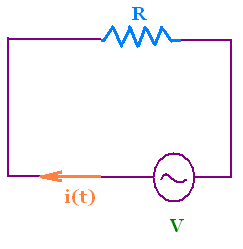 We consider a circuit which contains only a source and
a resistor, a purely resistive ac circuit.
We consider a circuit which contains only a source and
a resistor, a purely resistive ac circuit.
The loop rule across the circuit gives:
V - i R = 0, or
Vm sin(ωt) = i R
Hence
i = Im sin(ωt)
Where Im = Vm/R is the current
amplitude.
The phasor diagram gives another explanation on
how the voltage is related to the current in an ac-circuit.
A phasor is a rotating vector that
rotates about the origin with angular speed ω.
Its vertical component represents the sinusoidally varying
correspondent quantity. Its magnitude is equal to
amplitude of this oscillating correspondent quantity.
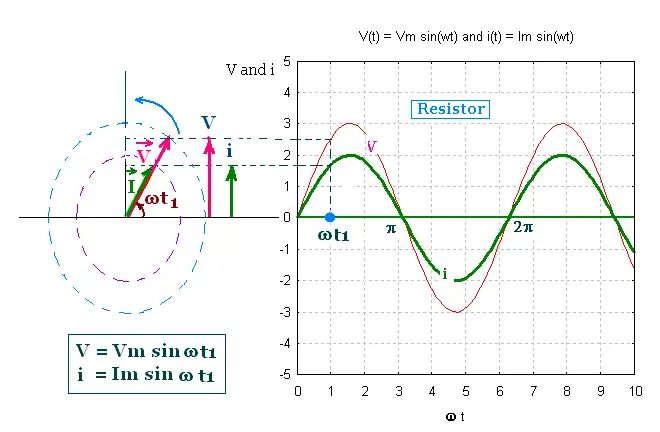
The potential difference across the source V and the
current I across the circuit are phasors. The vector
V represents the sinusoidally quantities V and I.
V = Vm sin(ωt), and i = Im sin(ωt)
are the vertical components of the phasors V and I. The magnitude
of the phasor V is Vm, and the magnitude of the
phasor I is Im.
In the purely resistive ac circuit, the voltage
V and the current i are in phase, that is the phase
angle difference between the voltage V and the current i is
zero. In the phasor diagram, The vector V and I and parallel.
The resistance limits the amplitude of the current in a
purely resistive circuit.
2. AC source connected to a capacitor
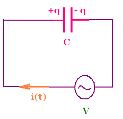
We consider a circuit that connects an ac source and a
capacitor only, a purely capacitive ac circuit
The loop rule gives V - q/C = 0 . or Vm sin(ωt) = q/C.
Using i = + dq/dt, we obtain: i = C Vm d sin(ωt)/dt
= Cω Vm cos(ωt)= Cω Vm sin(ωt + π/2)
= Im sin(ωt + π/2)
Where Im = Cω Vm is the current amplitude.
To write the expression of Im = Vm/(1/Cω) as
for a resistive circuit Im = Vm/R, we introduce, by
analogy to the resistance, the capacitive reactance Xc,
such that Xc = 1/Cω, and write:
Im = Vm/Xc.
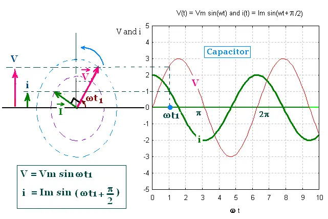
i = Im sin(ωt + π/2)
Im = Vm/Xc, and
Xc = 1/Cω
The SI unit of the capacitive reactance is the Ohm (Ω).
The capacitive reactance limits the amplitude of the current in a
purely capacitive circuit, similar the way the resistance does in
a purely resistive circuit. The capacitive reactance is a
frequency-dependent.
The oscillating quantities V and i are out of phase by π/2 rad.
As the phasor V and I rotate counterclockwise, the phasor V is π/2 rad
behind the phasor I.
In the graph of V and i versus ωt, the maxima in V come
π/2 rad later that the maxima in i. The voltage reaches its
maximum value later than the current by one-fourth of period
T/4 = 2π/4ω = π/2ω.
3. AC source connected to an inductor
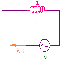
We consider a circuit that connects an ac source and an
inductor only (with a negligibly small resistance), a
purely inductive ac circuit.
The loop rule gives V - Ldi/dt = 0 . or Vm sin(ωt) = L di/dt.
Integrating di/dt with respect to time, we find
i = ∫ (Vm/L) sin(ωt)dt =
(Vm/L) ∫ sin(ωt)dt =
- (Vm/ωL) cos(ωt) + const.
If the current is steady (i = I), that is V is constant, then
V = Vm, thus sin(ωt) = 1. Therefore
ωt = π/2 and const = I. As the current i oscillates about
zero as it does V, and there is no steady current, then I = 0
and const = 0.
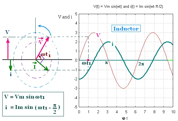
i = (Vm/ωL) sin(ωt - π/2)
= Im sin(ωt - π/2)
Where Im = Vm/Lω is the current amplitude.
To write the expression of Im = Vm/(Lω) as
for a resistive circuit Im = Vm/R, we introduce, by
analogy to the resistance, the inductive reactance XL,
such that XL = Lω, and write:
Im = Vm/XL.
i = Im sin(ωt - π/2)
Im = Vm/XL, and
XL = Lω
The SI unit of the inductive reactance is the Ohm (Ω).
The inductive reactance limits the amplitude of the current in a
purely inductive circuit, similar the way the resistance does in
a purely resistive circuit, or the way the capacitive reactance does in
a purely inductive circuit. The inductive reactance is a
frequency-dependent.
The oscillating quantities V and i are out of phase by π/2 rad.
As the phasor V and I rotate counterclockwise, the phasor V is - π/2 rad
behind the phasor I, or + π/2 rad ahead the phasor I.
In the graph of V and i versus ωt, the maxima in V come
π/2 rad before that the maxima in i. The voltage reaches its
maximum value before than the current by one-fourth of period
T/4 = 2π/4ω = π/2ω.
4. Series RLC in an AC circuit
4.1. The current in the circuit
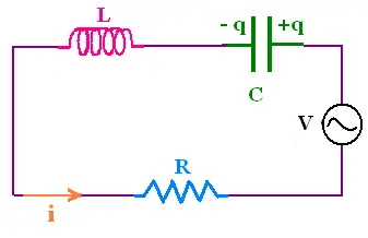
A series RLC circuit contains a resistor, capacitor, inductor,
and an ac source. The pool rule gives:
V = Ri + Ldi/dt + q/c (1)
where the voltage across the source is
V = Vm sin(ωt). The values of the five parameters
Vm, ω, R, L, C determine the current in the circuit.
Since the elements R, L, and C are in series, the current in
the circuit is the same.
The equation (1) is analogous to the equation of motion of the
forced, damped, harmonic oscillator. We shall use the phasor method
to solve this equation and find an expression for the ac current i.
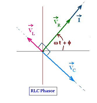
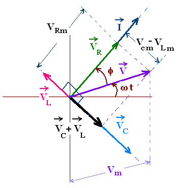
The phasor diagram for an RLC circuit is shows the three
vectors VR, VL, and VC.
VR is perpendicular to the VL, and VC, thus
to their difference VL - VC that are along the
same line and in opposite direction.
VR and I are parallel because they are just proportional.
The oscillating voltage V across the source sustains the oscillating
current i with the same angular frequency ω. The voltage V across
the source and the current i in the circuit are out of phase with
a phase difference φ between them. We write the current as:
i = Im sin(ωt + φ)
The phasor diagram will allows us to determine Im
and φ, hence the expression of i. The vertical component of the
phasor I is i = Im sin(ωt + φ).
To construct the RLC phasor diagram, we will use the
following facts:
- Since the elements R, L, and C are in series, the current in
the circuit is the same,
- The four phasors VR, VL, VC, and
I rotate counterclockwise,
- VR is parallel to I because the voltage across
the resistive element is in phase with the current,
- VC is π/2 rad behind I because the voltage across
the capacitive element lags the current by π/2 rad,
- VL is π/2 rad ahead of I because the voltage across
the inductive element leads the current by π/2 rad,
The lengths of these phasors are:
Vm = Vm
VRm = Im R
VLm = Im XL
VCm = Im XC
In the phasor notation, the equation (1) becomes vectorial
V = VR + VL + VC
This vectorial equation is written as:
Vm = VRm + (VCm - VLm). The
Pythagorean theorem gives
Vm2 = VRm2 + (VCm - VLm)2 =
Im2[R2 + (XC - XL)2]
Solving for Im we have
Im = Vm/[R2 + (XC - XL)2]1/2
,
that we can express as:
Vm = Z Im
,
with Z = [R2 + (XC - XL)2]1/2, called the impedance in the ac circuit.
Vm = Z Im, with
Z = [R2 + (XC - XL)2]1/2
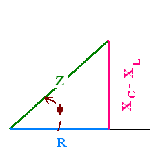
The phasor VR and I are parallel, the phase difference
π between V and i is the angle between the vector V and I. From
the impedance diagram, we have
tan(φ) = (VCm - VLm)/VRm =
(XC - XL)/R
RLC series circuit:
Vm sin(ωt)
i = Im sin(ωt + φ).
Im = Vm/Z
Z = [R2 + (XC - XL)2]1/2
φ = arc tan [(XC - XL)/R]
XC = 1/Cω
XL = Lω
4.2. Resonance in series RLC circuit
Resonance in a series RLC circuit driven by an
ac source is a feature that occurs when the oscillation in
the circuit takes a particular frequency, called the natural
frequency. When the angular frequency ω of the source
is near the natural frequency, the amplitude of the oscillation
becomes large. This is a feature of any system, as a harmonic
oscillator, driven by an energy oscillating source.
Let ω the angular frequency of the ac source in the RLC
circuit that can be varied, and ωo the natural frequency of this
circuit. Keeping fixed the quantities R, L, C and Vm, we
consider the current amplitude Im as we change the frequency of
the source ω. The amplitude of the current Im = Vm/Z
will be maximum when the impedance Z = [R2 + (XC - XL)2]1/2 is minimum, that is XC - XL = 0
or
XC = 1/Cωo =
XL = Lωo
Therefore ωo = 1/[LC]1/2, called the
resonance angular frequency.
Resonance angular frequency
ωo = 1/[LC]1/2
When ω = ωo, the amplitude of the current
is maximum Im = Vm/R.
Recall that the expression of the ωo is the same
as the angular frequency of oscillation for the Purely LC circuit,
with no resistor or source.
Resonance: Example
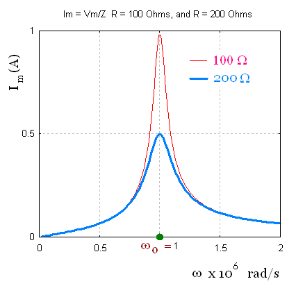
Vm = 100 V,
L = 1.00 mH,
C = 1.00 nF,
Case 1: R = 100 Ω and case 2: R = 200 Ω.
Since the product LC is the same for the two cases for the
resistance, the resonant frequency ωo
is also the same. ωo = 1/[LC]1/2 =
1.00 x 10⁶ rad/s.
At frequencies much less than ωo, the circuit
is predominantly capacitive. At frequencies much greater than
ωo, the circuit is predominantly inductive.
4.3. Power for a series RLC circuit
We want to examine the rate at which energy is exchanged
among the elements of the RLC circuit driven by the
energy ac source of voltage V = Vm sin(ωt).
That is the rate at which energy enters and leaves each of the
elements. The frequency of an ac source is too high regarding
the time dependence of these energy exchanges. Thus it is
convenient to consider these exchanges within a large
number of periods of oscillations, and take an average rate
at which energy is exchanged, that is an average power P.
How energy is exchanged in the RLC circuit ?
1. The source delivers electromagnetic energy to the circuit
that it had converted from some other form to electromagnetic energy.
2. The resistor dissipates electromagnetic energy as heat. Energy
leaves the circuit through Ri2 heating in the
resistor.
3. The current in the circuit oscillates sinusoidally, the energy
that enters the capacitor during the charging part of the
cycle is equal to the energy that leaves the capacitor
during the discharging part of the cycle. Therefore the
average power for the capacitor is zero
4. The inductor is an energy storage device as with the capacitor.
Therefore the average power for the inductor is zero
For the complete circuit, energy is supplied by the source
and used by the resistor. The average rate of this energy
transfer is the average power P for the circuit.
The power P for the circuit is equal to the product of V and i.
V = Vm sin(ωt), and i = V/Z = Im sin(ωt + φ).
Thus P = V i = V2/Z = (Vm2/Z) sin2(ωt)
= R sin2(ωt + φ).
The average power P for the circuit is equal to the
average of P. That is P = Average (P) = Average ((Vm2/Z) sin2(ωt)) = Average (R Imsin2(ωt + φ))
We use use the rms: root-mean-square method to
find the expression of P.
The voltage V or the current i are two sinusoidally varying
quantities, These two sine functions oscillate symmetrically
about zero. Hence, their average is zero. However the power P
involves the square of a sine function which is always positive
and oscillates symmetrically about +1/2. Thus the average value of
sin2(ωt + φ)) is + 1/2. Therefore
V = Average (V) = Average (Vm sin(ωt)) =
Vrms = [V2]1/2 = Vm/√2.
and
i = Average (i) = Average (Vm sin(ωt)/Z) = (Vm/Z)/√2 =
Irms = (Im)/√2.
The values given for an ac voltage or current are the rms values.
AC voltmeters ans ammeters are calibrated to measure rms values. The
voltage across the terminals of an electric outlet in houses is 120 V
which refers to the rms value of the voltage. The amplitude of this
voltage is Vm = Vrms x √2 = 120 x √2
= 170 Volts.
The average power for an RLC circuit driven by
an ac source is evaluated from the instantaneous power P
dissipated in the resistor.
P = R i2 = R Im2 sin2(ωt + φ)).
P = Average (P) = ((Vm2/Z) sin2(ωt))
= Vrms = R Im2 =
Only the resistor is involved in this power. The average
power P is the power dissipated in the resistor.
P = R Irms2.
Power dissipated in the resistor
P = R Irms2
This expression is similar to the expression giving the
power dissipated in a resistor in a dc current, the dc
current is replaced by rms current.
We can express P another way in terms of the
product Vrms and Irms, where Vrms
refers to the rms value of the voltage across the source and Irms
refers to the rms value of the current through the RLC circuit.
We have Vm = Im Z. Dividing by √2 gives
Vrms = Irms Z, hence
P = R Irms2 = R Irms (Vrms/Z) =
(R/Z) Irms Vrms.
From the RLC impedance diagram, we have cos φ = R/Z. The
average power becomes
P = Irms Vrms cos φ.
cos φ is called the power factor .
Average power for RLC series circuit:
P = Irms Vrms cos φ
cos φ is the power factor .
At resonance frequency, cos φ = 1, and
P = Irms Vrms
|
|