|
Electrostatics
Electromagnetics
Electricity &
Magnetism
© The scientific sentence. 2010
|
Kirchhoff's rules
An electric circuit contains ordinarily batteries (or other sources),
resistors, inductors, and capacitors of known values. To determine the
current crossing the circuit elements, we use Kirchhoff's rules
referred as the loop rule and the junction rule.
1. The loop rule
The loop rule is a statement of conservation of energy within
the circuit because the electric potential is directly related to
the potential energy of the carriers. This rule states:
The sum of the potential differences encountered in a complete
round-trip around any closed loop in a circuit is zero.
That is: ΣVi = 0.
Loop rule:
ΣVi = 0
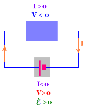
Before using the loop rule, we define the sign convention for the
current along the circuit:
The current I is positive when its sense
corresponds to the direction og motion of positive charge carriers.
The current is positive
for positive carriers.
2. Examples
2.1. Example 1
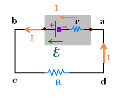
Choosing the counterclockwise sense, we have:
Vb - Va = ℰ - r I
Vc - Vb = 0
Vd - Vc = - R I
Va - Vd = 0
ΣVi = 0
(ℰ - r I) + 0 + ( - R I) + 0 = 0
Solving for I, we find:
I = ℰ /(r + R)
Now, if we chose the clockwise sense, we get:
The potential across the battery decreases: Va < Vb
so ΔV < 0, and the current I is < 0. Hence the potential difference
across r is > 0 . Therefore
Va - Vb = - ℰ + r I
Continuing to traverse the loop, we have:
Vb - Vc = 0
Vc - Vd = + R I
Vd - Va = 0
The loop rule gives:
- ℰ + r I + R I = 0. That is
I = ℰ /(r + R)
Which is the same result as before.
The result is independent of which way we go around the loop.
2.2. Example 2
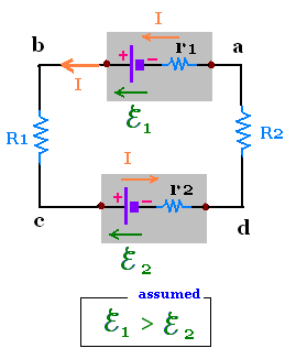
Vb - Va = ℰ1 - r1 I
Vc - Vb = - R1 I
Vd - Vc = - ℰ2 - r2 I
Va - Vd = - R2 I
ΣVi = 0
ℰ1 - r1 I - R1 I
- ℰ2 - r2 I - R2 I = 0
ℰ1 - ℰ2 =
r1 I + R1 I - r2 I + R2 I
I = (ℰ1 - ℰ2)/(
r1 + R1 + r2 + R2)
If ℰ1 > ℰ2 then I has a
positive value, and the sense of the current is counterclockwise
as we assumed before writing the loop rule.
If ℰ1 < ℰ2 then I has a
negative value, and the sense of the current is clockwise
opposite our assumed sense.
Generally, the rule is: If we assume a particular sense for the
current at the outset of a problem, and the value of the current
turns out to be negative, then this means that the actual sense
of the current is opposite the assumed sense.
In more complex circuits, we often cannot predict the sense of the
current with certainty at the outset of the analysis.
It is the equation solved for the current that tells us automatically
its sense in the circuit.
3. The point rule or junction rule
The point rule is a statement that comes from the
conservation of charge since charge does not accumulate
at any point along the connecting wires. It states that
the sum of the currents at a junction is zero:
ΣIi = 0
In other way The sum of the currents toward a branch point is
equal to the sum of the currents away from the same branch point.
ΣItoward = ΣIaway
point rule:
ΣIi = 0
Or
ΣItoward = ΣIaway
3.1. Example 1: Two loops
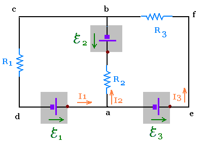
We assume the sense of the currents I1 and I3 are
counterclockwise and for I2 clockwise. The equations of the
currents will tell us whether these choices are true or wrong.
If these assumptions turn out to be wrong, just change the sign of the
related current to obtain the actual current, the magnitudes of
the currents remain the same.
For simplicity, we include the internal resistance of each battery
in the resistance that is in series with that battery.
Loop dabc:
ℰ1 - R2 I2 - ℰ2 - R1 I1 = 0
Loop aefb:
ℰ3 - R3 I3 + ℰ2 + R2 I2 = 0
Loop defc:
ℰ1 + ℰ3 - R3 I3 - R1 I1 = 0
We have three unknowns I1, I2, and I3.
On of these equations is irrelevant because it is obtained from
two others. Hence we keep just two of them: the first and the third
equations.
Point a:
I1 = I2 + I3
Substituting this value in the first equation
(loop dabc), we obtain:
ℰ1 - ℰ2 = R1 I1 + R2 I2 =
R1 (I2 + I3) + R2 I2 =
(R1 + R2)I2 + R1 I3)
Finally, we have the two equations:
ℰ1 - ℰ2 = (R1 + R2)I2 + R1 I3)
(Eq. 1)
ℰ1 + ℰ3 = R3 I3 + R1 I1
(Eq. 2)
Substituting one in the other, we find:
I2 = [ℰ1 - (R1/R3)ℰ3 - (1 + R1/R3)ℰ2]/[R1 + R2 + (R1 R2/R3)]
Using the equation (Eq. 1) , we find I3, and the equation
of the point a , we find I1.
3.2. Example 2:Electrical Bridges
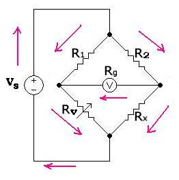
3.2.1. Wheatstone bridge:
The Wheatstone bridge is used to measure an unknown resistance.
In this figure, Rx is the unknown value of a resistance to be measured,
and Rv is a variable resistor. The idea is to vary the resistance Rv until
the galvanometer (resistance Rg and voltage Vg) indicates zero.
Once this condition is achieved, we can find the value of Rx. Indeed:
We have:
Ig + I1 = Iv
Ig + Ix = I2
R2 I2 + Rg Ig - R1 I1 = 0
Rv Iv - Rx Ix + Rg Ig = 0
Ig = 0 implies:
I1 = Iv
Ix = I2
R2 I2 = R1 I1
RvIv = Rx Ix
Then:
Rx = Rv Iv / Ix = Rv I1/I2 = Rv R2/R1
Rx/Rv = R2/R1 (1)
We can also express the value of the voltage Vg depending
on the value of the voltage source Vs:
Vs = R1I1 + Rv (I1 + Ig) → I1 = (Vs - RvIg)/(R1 + Rv) (a)
Vs = R2I2 + Rx (I2 - Ig) → I2 = (Vs + RxIg)/(R2 + Rx) (b)
We have:
Vg = R1I1 - R2I2
With the equations (a) and (b), we obtain:
Vg = Vs(R1/(R1 + Rv)) - Vs(R2/(R2 + Rx)) - Ig[R1Rv/(R1 + Rv) + R2Rx/(R2 + Rx)]
As Ig is very small, then the term if Ig is negligible, we have finally:
Vg = [R1/(R1 + Rv)- R2/(R2 + Rx)]Vs
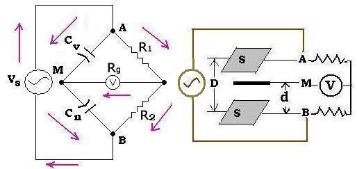
3.2.2. Modified Wheatstone bridge: Sauty Bridge:
It is used to measure a level or pressure of a liquid in a container. It
contains two capacitors and two resistors.
We have the same reasoning as for the Wheatstone bridge. Since the current is alternating, the
expressions of the currents and voltages are effective quantities. The impedance of a capacitor is
Z = 1/Cω (ω is the frequency of the alternating current), as in the relationship (1), we have:
R2 / Cω = R1/Cn or
Cn/Cv = R1/R2 (2)
The expressions of the two capacitors are:
Cn = ε0 εr S / d
Cv = ε0 εr S / (D - d)
Then:
Cv/Cn = d/(D - d) = (d - 1)/D
The distance "d" is fixed and known, so is the value of Cn. If the distances "D" changes;
then the distance "D - d" between A and M changes; that gives a new value of Cv; according
to the value of Cn.
The expression, as for the Wheatstone bridge, of the voltage V takes the expression:
V = [Cn/(Cv + Cn) - R1/(R1 + R2)]Vs
We can write:
V = [1/(Cv /Cn + 1) - R1/(R1 + R2)]Vs = [(D - d)/D - R1/(R1 + R2)]Vs
V = [(1 - d/D) - R1/(R1 + R2)]Vs
For each displacement "D - d" or "D", we have directly a value measured in the galvanometer V.
This is the principle of a flow transmitter of a fluid.
Application:
D = 10 cm , d = 4 cm, R1 = R2 = R3 = 5 kΩ, Vs = 110 Volts
V/Vs = (10 - 4)/10 - 5/(5 + 5) = 0.6 -0.5
V = Vs/10 = 110/10 = 11 Volts
For a distance of 6 cm, we get 11 Volts in the galvanometer.
|
|