Current and resistance
Electrostatics deals with stationary charges. In this chapter we
are going to consider moving charge carriers are electric conduction.
When a conductor carries charges, the excess of charges resides on the
surface of the conductor. Hence the electric field inside is zero.
However, if we maintain a nonzero electric field inside the
conductor, say we connect it to a battery, then the conductor's
charge carriers will flow and an electric current will
exist. The current in the conductor can be steady that is
constant, or varying in time as an alternate current.
When an externally electric field is applied to a conductor,
it exerts a force on each of the conductor's charge carriers and
causes them to move through the material.
A conductor is a material in which some of the
charged particles are free to move. These particles are the
conductor's charge carriers. Metal is an example of a conductor
in which the positive charge are fixed ions, and only electrons can
move around. The electrons are the metal's charge carriers.
1. Electric current
1.1. Definitions
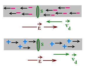
The electric current through a circuit is a flow of charges.

Consider charge carriers moving in a conductor wire under an
electric potential, then an electric field E . The field E
across the conductor is oriented from (+ charges) to (- charges).
Hence the positive charge carriers move in the direction of E and the
negative charge carriers move in the opposite direction of E.
Let dQ be the magnitude of the charge that passes through the
plane cross-sectional surface S in time dt. The electric
current I in the wire is the rate at which charge passes through
this surface: I = dQ/dt.
I = dQ/dt
The SI unit of electric current is the ampere (A) equal to
the coulomb (C) per second (s): 1 A = 1 C/s.
Electric current is a scalar quantity. The sense of
a current is defined as the direction of the motion of
positive charge carriers.
1.2. Drift velocity of the charge carriers
The motion of the charge carriers in a conductor is due to an
external electric field applied to the conductor. This field
exerts electric forces on the carriers that causes them
to move through the conductor.
If the electric forces were alone
in the conductor, the charge carriers would move with
a constant acceleration under the constant electric field. But in addition
to the electric forces, the carriers interact with the other particles
in the material. The combined effect of this interaction and the
applied electric field causes the charge carriers to move with a
constant average velocity called the drift velocity vd.

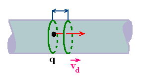
Let n be the number density of charge carriers in the wire,
that is the number of carriers per unit volume, and q the charge
on each carrier.
The number of charge carriers in the cylinder S dl is n S dl.
The magnitude of the charge dQ that passes through S during the
time dt is n S dl q. Hence
I = dQ/dt = n S q dl/dt = n S q vd
vd is the drift speed of a q charge carrier.
I = dQ/dt = n S q vd
1.3. Electric current density
Electric current I characterizes the flow of charge through
the entire cross section of a conductor.
Electric current density J
describes the flow of charge at a point within a conductor. The
current density is a vector quantity. The direction of J is the same
as the direction of the vector drift velocity vd.
If the current density is uniform, its magnitude J is equal to the
current I divided by the cross-sectional area S of the wire:
J = I/S = n q vd
Notice that J points in the direction of vd
for positive carriers and points it points opposite vd
for negative carriers; that is J points in the same direction as I.
→
→
J = n q vd
2. Resistance and Ohm's law
2.1. Resistance and Ohm's law
When a potential difference V is applied across a conductor,
such as a metal wire, a current I is produced in the conductor.
The produced current for each amount of applied voltage depends
on a property of the conductor called the resistance.
The resistance R of a conductor is defined as
R = V/I
It is the measure of the opposition of the conductor to
the flow of charge. The correspondent circuit element is called
resistor, with a symbol . .
The empirical formula of proportionality between V and I , written as
V = R I , is called Ohm's law.
The SI unit of the Resistance is the Ohm (Ω).
1 Ω = 1 V/A (Volt/Ampere).
Ohm's law:
V = R I
Materials that obey Ohm's law are ohmic, and the materials
that not obey Ohm's law are called non-ohmic. A resistor is ohmic, but
a capacitor or inductor are non-ohmic.
2.2. Resistivity
2.2.1. Definition
Consider a section of conductor of length l and cross section la area S.
The resistance of this section depends on the length l, the
area S, and the material or the substance that composes this section.
Experiments show that the resistance is proportional to the length
l and inversely proportional to the area S. Therefore
R = ρ l/S
R = ρ l/S
The coefficient of proportionality ρ is called resistivity.
The SI unit of the resistivity is the Ω.m (Ohm x meter). at 20°C,
resistivities range from 1.58 x 10⁻⁸ for Silver to
7.50 x 10¹⁷ for Quartz.
2.2.2. Dependence of the resistivity on the temperature
The resistivity depends also of the temperature according the formula
ρT = ρo [1 + α(T - To]
ρT = ρo[1+α(T-To]
To is a reference temperature, and α is the
temperature coefficient of resistivity. The SI unit of α
is 1/K, where K is the Kelvin degree.
Example:
For Copper:
At 20°:C
ρ = 1.67 x 10⁻⁸ Ω.m.
α 3.90 x 10⁻³ K-1.
At 900 °K (627 °C)
ρ ≈ 6.00 x 10⁻⁸ Ω.m.
(°K = 273 + °C)
2.2.3. Relation between electric field and current
density
The vector current density J at a point in a conductor is
the flow of charge at this point, whereas the scalar electric
current I is the flow of charge through the entire
cross section S of the conductor. If J is uniform, then
it is given by J = I/S, and has the same direction
as the drift velocity vd. Hence, when a
potential difference V is applied to a conductor, that is
an electric field E is applied to a conducting material, a
current I then a current density J is produced in the material.
The current density at a point in a conductor depends on the
electric field at that point.
Consider E and J uniform within a section of a conductor
of length l and cross sectional area S under a potential
difference V and crossed by an electric current I. We have:
J = I/S and V = E l.
Ohm's law gives
V = E l = R I = R J S
Where R is the resistance of the section of the conductor.
Solving for J, we obtain
J = E l/R S = (l/RS) E
The constant l/RS is a characteristic property of the material:
l is its length, S its cross section area, and R is its resistance.
This constant is called the the conductivity σ of the
section of the conductor. Therefore
J = σ E
A material that has a large conductivity than another will have
a large current density for the same electric field.
The conductivity of a material is a measure of the
material's ability to allow charge carriers to flow through it
.
In terms of the resistivity ρ = RS/l of the material, we have:
J = (Sl/Sρl)E = (1/Sρ)E or
E = ρ J
Electric field and current density in a conductor: Vectorial
expression of Ohm's law:
→ →
J = σ E
→ →
E = ρ J
3. Resistors in series and parallel
The combination of resistors can be made in series or
in parallel. The equivalent resistance of a combination
of resistors is the resistance of a single resistor which, if
used in place of the combination, would produce the same
external effect.
To produce the same external effect as a combination of
resistors, this single resistor must carry the same current
as the combination when the potential difference across it
and across the combination are the same.
3.1. Resistors in series
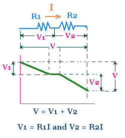
 Consider two resistors with resistance R1 and R2
connected in series under the potential difference V1 and V2.
We have :
V = V1 + V2.
The current I in each resistor is the same.
Hence
V1 = R1 I, and V2 = R2 I
V = R1I + R2I =
(R1 + R2)I = ReqI
Thus, the equivalent resistance R12 is
R12 = V/I = R1 + R2
More generally,
Req = ΣRi
for each resistor i in the circuit.
Resistors in series:
Req = ΣRi
3.2. Resistors in parallel
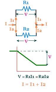
 Consider two resistors with resistance R1 and R2
connected in parallel. The potential difference is the same:
V = V1 = V2
The current I in the main branch is equal to the sum
of the currents I1 and I2 in th e
resistors 1 and 2.
I = I1 + I2
Since V1 = R1 I1 , and
V2 = R2 I2, we have
I = V/R1 + V/R2 = V(1/R1 + 1/R2)
Therefore, the equivalent resistance R12 is
given by:
1/R12 = 1/R1 + 1/R1
More generally, for more that two resistors connected in
parallel,
1/Req = Σ 1/Ri
Resistors in parallel:
Req = Σ 1/Ri
|