|
Electrostatics
Electromagnetics
Electricity &
Magnetism
© The scientific sentence. 2010
| Electromagnetics: The magnetic field
Magnets attract small pieces of iron as the earth attracts masses.
The magnet produces a magnetic field that attracts charges
objects. This interaction is called magnetism.
Electric current is also a source of magnetism, discovered by
Hans Christian Oersted in 1891. This is electromagnetism,
that is electricity and magnetism. When the current is constant
in time, we deal with magnetostatics.
Phenomena related to both electric field and magnetic
field deal with electromagnetics, that started with
the experiments of Faraday and Joseph Henry. James Clerk Maxwell
synthesized all in some equations.
Quantum theory gives a microscopic theory of magnetic materials.
In this chapter, we will consider the effect of a magnetic
field on electric charges and currents.
1. The magnetic field

As an electric field E that exerts a force F = q E in a
charged particle q, the magnetic field does the
same thing for a moving charged particle. Experiments
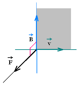
show that the exerted force F by a magnetic field B on
a moving charged particle q is directed in the plane
perpendicular the plane formed by the velocity v of the
particle and the magnetic field B: F ⊥ plane(v,B).
The expression of the magnetic force F is
| → |
|
→ → |
|
| Fm = q |
|
v x B = qvB sin θ |
|
| |
|
|
|
θ is the angle between v and B.
The SI unit of magnetic field is Newton/Cm/s = T tesla.
We use also the gauss (G).
1 T = 104G. The magnitude of the magnetic
field of the earth near the surface is about 0.3 G. In the
laboratory, the largest produced is about 30 T.
Note that, if the charged particle is not accelerated, its
velocity is constant and any infinitesimal displacement
can just be written as dl = v dt, during the time dt.
Therefore dl and v are parallel and since F is perpendicular
to v, it is also perpendicular to dl, hence the work
done by the magnetic force on the charged particle is zero
. A static magnetic field does no work on a charge,
but an electric field does.
2. Force on a current-carrying conductor

A current in a conductor is a set of charged particles
(or charge carriers) moving at certain average velocity vd
called drift velocity.
Therefore, the previous equation can
be used to determine the magnetic force on that conductor.
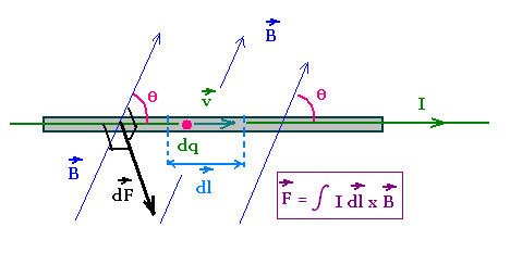
Consider a thin and straight wire crossed by a current I = dq/dt.
So dq = I dt.
Substituting this equation in dF = dq vd x B, we obtain
the infinitesimal magnetic force on the element dl of the wire:
dF = dq vd x B = I dt vd x B = I dl x B,
where dl = vd dt is the infinitesimal displacement
of the charge carriers at the drift velocity vd. I dl
is the correspondent infinitesimal current element.
Integrating gives:
F = ∫ I dl x B
Magnetic force on a current-carrying conductor:
F = ∫I dl x B
3. Magnetic force on a half-ring
current carrying wire

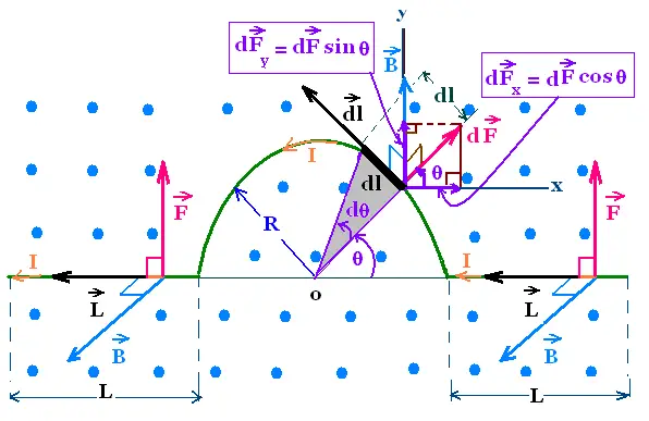
Consider a half-ring wire in a uniform
magnetic field B perpendicular to the plane of the figure,
that points out. The conductor has two straight
segments, at left and at right, with length L parallel
to the x-axis. A semicircle of radius R, links the two
segments. The conductor carries a current I.
We are interested to find the total magnetic force on the whole wire.
At left and right, both the two magnetic forces are
directed upward on the y-axis. Their magnitude
has
Fl = Fr = ∫ B I dl sin 90° =
B I ∫ dl = B I L each.
Therefore
On the two
segments, the magnetic force is
Fs =
Fr + Fl = 2 B I L
On the semicircle, the magnetic force dF acts
on the element dl = R dθ. This force
is "centrifugal".
This force dF has two components:
On x-axis: dFx = dF cos θ, and
On y-axis: dFy = dF sin θ
Therefore the force on the entire semicircle
has the components:
Fx = ∫ dF cos θ =
∫ I dl x B cos θ =
∫ I R dθ B cos θ =
B I R ∫ cos θ dθ
Fx = B I R ∫ cos θ dθ = 0
θ : 0 → π
And
Fy = B I R ∫ sin θ dθ = 2 B I R
θ : 0 → π
Fx = 0
Fy = 2 B I R
The total magnetic force, oriented
to the y-axis is then:
F = 2BIL + 2BIR = BI(2L + 2R)
It is exactly the same force if we replace
the semicircle with a straight segment
along the x-axis between the ones on the
left and the right.
4. Torque on a current loop

A magnetic field exerts a force on a current carrying
wire. About an axis, in a current loop, the magnetic
field produces a torque.
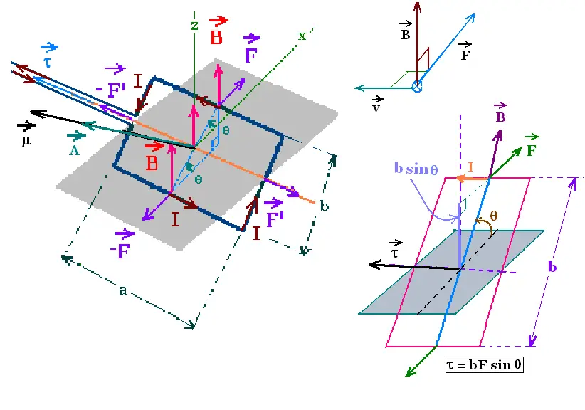
Consider a rectangular loop of dimensions a and b. carrying
a current I, in a uniform magnetic B directed down-up.
The area of the plane of the loop is A = ab. The vector area
A defines the orientation of the loop. The right hand rule
following the sense of the current determine the orientation
of the vector A. The direction of A is perpendicular
to the plane of the loop.
The magnetic force on each straight segment of the loop is
F = ∫ I dl x B = B I ∫ dl = B I l.
on the upper element: F = B I a
on the lower element: - F = B I a
on the right element: F' = B I b
on the left element: - F' = B I b
The two forces (F', - F') add to zero. They produce no torque
because they
are on the rotation axis.
The two forces (F, - F) add to zero before the loop is pivoted.
They produce a torque τnet on the loop about the x-axis.
The magnitude of the net torque is:
τnet = τF + τ-F =
+ F (b/2) sin θ + F (b/2) sin θ = F b sin θ =
B I a b sin θ = B I A sin θ.
The right-hand rule gives the direction of the torque which
is the direction of the cross product A X B (from the right to
the left).
Since θ is the angle between the two vector magnetic field B
and the vector area A, the magnetic torque takes the form:
τnet = IA x B
This result is valid for a loop of any shape carrying a
current I, in a uniform magnetic field. Especially for a turn
of wire or a coil with N turns forming an area of A. The torque
on each turn is τ = IA x B. Thus the torque produced by
a coil of N turns is τcoil = Nτturn = NIA x B.
The magnetic torque on the coil of N turns carrying
a current I, in a uniform magnetic field B, is :
4. Magnetic dipole moment
The magnitude of the magnetic torque varies with the position of
the current carrying. When the the vector A and the vector B are
parallel (as the position before pivoting the current loop), the
magnetic torque is zero. This position is the rotational
equilibrium position of the current loop.
Once the loop leaves this position, the magnetic
torque tends to align the current loop at the equilibrium
position. This effect occurs, of course, with a bar magnet
in a uniform magnetic field in which the torque tends to
align the north pole with sense of the magnetic field. This
is exactly what it happens with an electric dipole
in an electric field.
The orientation of an electric dipole in a uniform
electric field is the equilibrium position in which the
dipole moment P and the electric field E are aligned.
Since the electric potential energy
U = - P.E =
- P E cos θ, then U = 0.
θ is the angle
between P and E.
The torque of an electric dipole τ that tends
to align P with E is
τ = P x E
In analogy, we define a magnetic dipole moment μ
of a current carrying conductor, in a uniform magnetic
field B by the torque τ applied on this magnetic dipole
moment μ as:
For a coil with N turns, the torque is:
τ = μ x B = NIA x B
Which gives:
μ = NIA
The SI unit of magnetic dipole moment is A.m2
.
In analogy with the electric dipole, we define
the potential energy for the magnetic dipole
U = - μ . B = - μ B cos θ.
θ is the
angle between the vectors μ and B.
|
|