|
Electrostatics
Electromagnetics
Electricity &
Magnetism
© The scientific sentence. 2010
| Motional emf's
1. Motional emf's
In a stationary loop or coil, an emf is induced if the
magnetic flux linking it changes. Because the expression
of the magnetic flux is:
→ →
ΦB = ∮ B . dS
The magnetic flux can change in three manners:
1 - The magnitude of the field changes, or
2 - The surface crossed by the field changes, or
3 - The orientation of the circuit that link the flux changes.
Changing the orientation of the
conductor circuit, or its surface leads to a motional emf. This
process converts mechanical energy to electric energy.
2. Applications
2.1. sliding wire circuit

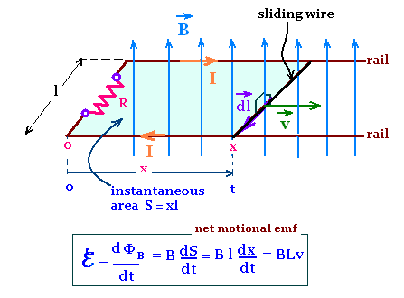
Consider a sliding wire circuit with an U-shaped conductor at rest
in a region of uniform magnetic field B perpendicular to the plane
of this circuit.
On the two rails of the circuit, moves a conducting wire of length l
that slides on the rails of the circuit with a constant velocity v parallel
to the rails, then perpendicular to B.
The sliding wire moves, then the charge carriers in it also
move. Therefore, the magnetic field exerts a force F on each
charge carrier q:
→ → →
F = q v x B
This magnetic force is responsible of circulating the
charge carriers along the circuit. giving rise to an induced
current, the an emf ℰ through the resistor R.
The moving charge carriers in the wire are electrons, v x B points
in the dl direction, hence F = (- e) v x B points in the opposite
direction, thus the sense of the current is in dl direction.
Moving he wire from the left to the right, increases the surface
crossed by the magnetic field B from Si = xl to Sf = (x + dx) l, hence
the flux ΦB of the magnetic field B increases
from ΦBi = B x l to ΦBf = (x + dx)Bl.
The change in the magnetic flux is then dΦBi = ΦBf -
ΦBi = B l dx. Therefore, the rate of change of the
magnetic field is: dΦBi/dt = B l dx/dt = Blv = ℰ
In addition to the magnetic force, there are other forces (for
example due to the Hall effect) that contribute to the net emf ℰ.
Induced emf for a sliding-wire circuit in uniform magnetic field
ℰ = B l v
2.2. Generators and alternators
Faraday's law is the basis of the conversion of mechanical energy to
electrical energy. Electric generators and alternators
use this principle of conversion.
2.2.1. Generators

A generator (dynamo) contains mainly a conducting coil
rotating in a uniform magnetic field.
The induced electric current is collected in an external
circuit via brushes on rotating rings.
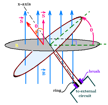
Consider a simple representation of a generator with
a circular loop rotating about the x-axis perpendicular
to a uniform magnetic field B.
The flux linking the loop is:
→ →
→ →
ΦB = ∫ B.dS = B.S = B S cos θ
The loop rotates, then the angle θ is changing, therefore
the flux is changing that leads to un emf.
If the loop rotates at constant angular speed ω about the
x-axis, then θ = ωt, thus ΦB = B S cos ωt.
The emf becomes:
ℰ = - dΦB/dt = B S ω sin ωt.
With n turns in a coil,
we have: ℰ = n B S ω sin ωt.
The emf oscillates, the induced current is then an
alternating current: ac. So the generator is called
an ac generator.
ac generator:
ℰ = n B S ω sin ωt
To obtain a direct current or a dc generator, we change
the connection. Instead of having two rings as in the ac current, we
make connection between the loop and the external circuit with
a split-ring commutator. By this switch, the sense of the output
voltage remains the same that leads to a dc current.
2.2.2. Alternators

The values of the currents in generators or relatively small
because of the large number of turns that leads to a large
resistance in the coil circuit. Large values of currents as
some ten of Amperes cannot be handled by the electrical contacts
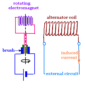
like brushes and commutators. To avoid this, we use rotating
magnets or rotating electromagnets that induce emf in another
stationary coil without sliding contacts or brushes, which
will carry the large current in the external circuit. This
is the principle of an alternator.
Brushes are used in alternator to supply a smaller currents to
rotating electromagnets.
|
|