|
Electrostatics
Electromagnetics
Electricity &
Magnetism
© The scientific sentence. 2010
|
Transformers
1. Description:
A transformer is an AC electric device used to change voltage or
current. Its simplest form consists of two windings wrapped around
a core. The windings which are a set of coils ( as a solenoid) are not electrically
connected, but they are coupled by the magnetic field due to these two windings
themselves. One is called the primary winding, the second is called
the secondary winding. The supplied primary AC current produces the
magnetic field, then the related magnetic flux links the second winding. The
AC flux induced through this secondary winding produces an AC voltage. Once an
impedance is connected to the secondary winding, an AC electric current
is supplied. The transformer can then transform voltage or current. An iron
core is used to direct and increase the magnetic field created by the
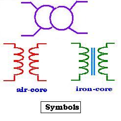
primary winding. We use the following symbols as shown in the figure.
2. Ideal transformer
An ideal transformer is considered as it does not contain any resistor,
no power losses within the core, and no leakage flux from the two windings.
If an AC voltage source U = Uocosωt is applied to the
primary part, then the emf raised on the primary winding is equal to the
voltage U. According to Faraday's and Lenz's laws E = - dΦ/dt = - LdI/dt,
where Φ = BS, "B" is the magnetic field due to the changing AC electric
current and "S" is the area of one coil of the winding. L is the inductance
of the winding, and I is the electric current that passes through the circuit.
The electric current "I" takes then the form:
I = (- 1/L) E dt = (- 1/L) U dt = (- Uo/L) cosωt dt =
(- Uo/ωL) sinωt = - Io sinωt.
(We have integrated over t, and have I = 0 at t = 0, and let: Io
= Uo/ωL).
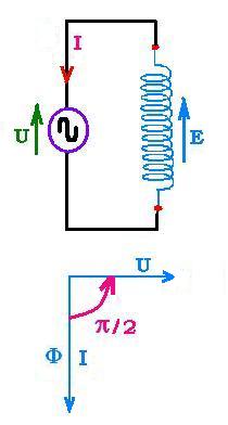
We can write the expression of I as: I = - Io sinωt =
Io cos(ωt + π/2).
With the following results:
U = Uocosωt
I = Io cos(ωt + π/2) ,
We can remark then that the current I and the voltage U are in time quadrature
because the winding (coil) current lags behind the coil voltage by π/2.
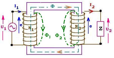
1. Flux across a coil:
If Φ1 is the magnetic flux in the primary created by
the changing AC current, its induced related emfs e1s
= - L dI1/dt; where I1 is the electric current across the
primary and L1 is the self-inductance of one coil of the
primary winding. This flux Φ1 induces an emf e2
across a secondary coil, then an AC current which gives rise to an emfs
e2s and a flux Φ2. Thus, inside the secondary, we have:
e = e2 + e2s and
Φ = Φ1 + Φ2.
The flux Φ2 contributes to an emf e1 across the
primary windings. Thus, inside this primary, we have :
e = e1s + e1 and
Φ = Φ1 + Φ2.
2. Flux across a winding:
Inside the core we have Φ = Φ1 + Φ2
If N1 and N2 are respectively the numbers of turns
inside the primary and the secondary winding, we can write:
U1 = - N1 dΦ/dt
U2 = - N2 dΦ/dt
Hence:
U1 /U2 = N1 /N2
The electric apparent power "S= U I" remains the same from the
primary to the secondary, that is
U1 I1 = U2 I2
We have the following relationship:
U1/U2 = N1/N2 = I2/I1 = α
3. Real transformer
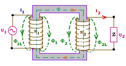
In the real transformer windings have resistance and three kinds of magnetic flux
losses.
3.1. The losses
The first loss is the leakage, that results from
an imperfect magnetic linking of one winding to another. The second loss
is due to the Eddy currents or Foucault's currents that take place within the
core and due to the time varying magnetic field exists inside a ferromagnetic material;
this why a core is generally laminated in order to cut these currents and
minimise this loss. The third loss is due to the hysteresis effect inside the
core material. Eddy currents and hysteresis are ferromagnetic losses.
 The origin of these circulating Eddy currentc is the rotation of the atoms in
order to align with the applied varying magnetic field. The Eddy current opposes
the change in the magnetic field. Moving a conductor within a constant
magnetic field generates also an eddy current, that tends to stop it. The power
related loss empirical relationship is ΔPe = Keƒ2Bmax2;
where Ke is a constant, ƒ the frequency and Bmax the
maximum magnitude of the magnetic intensity.
The origin of these circulating Eddy currentc is the rotation of the atoms in
order to align with the applied varying magnetic field. The Eddy current opposes
the change in the magnetic field. Moving a conductor within a constant
magnetic field generates also an eddy current, that tends to stop it. The power
related loss empirical relationship is ΔPe = Keƒ2Bmax2;
where Ke is a constant, ƒ the frequency and Bmax the
maximum magnitude of the magnetic intensity.
Hysteresis effect is due to the fact that the magnetic density B
and the magnetic intensity H are not proportional. The magnetic intensity
decreases rapidly that the magnetic density. The related power loss empirical relationship
is ΔPh = KhƒBmax2.
Combining the two losses, the total core power losses is:
ΔPferro = ΔPe+ ΔPh
|
|